The Owon oscilloscope .bin file format
The oscilloscope software is a bit dodgy - or at least I don't quite understand how it works or why it works this way.
So I decided to reverse engineer the .bin file format to be able to write my own program to show and manipulate the data.
File header
I already figured out that the file is exactly 69 bytes longer than the buffer depth. So for a 10k buffer the file size is 10069 bytes and for a 1k buffer it's 1069 bytes,
This makes sense since the scope has an 8 bits resolution so that's 1 byte of data plus a 69 byte header.
A saved wave with no signal input indeed shows that from byte 70 on there is a whole range of 00 FF 00 FF 01 FF 00 FF etc. data in the file: this must be the 2's complement value of the signal (0, -1, 0, etc).
The header reads as:
0000 53 50 42 53 30 34 ff ff ff 00 43 48 31 b8 d8 ff |
Thanks to this blog I was able to get a bit further in my search for the file format.
There is a 10 bytes header (SPBS04....), then 3 characters to denote the used channel (CH1) and then there are 14 32 bits integers to specify a number of things.
Here is what I have figured out until now:
0000 53 50 42 53 30 34 ff ff ff 00 SPBS04.... = 10 byte header |
- Start/Length of display: a quick test (changing some samples in the .bin file) show that the start position is the sample index that is the first one on the screen and the length is the length of the screen buffer.
A length of 6080 may seem strange but this is due to the fact that the timebase has 15.2 divisions showing.
(note: still to confirm with other samples) - Sample size: not too hard to guess. Although I have only tested with 10k sample buffers I think it is quite OK to assume this is correct.
- Timebase: An index is used to result in the final setting. The timebase goes from index 0 (1 ns/div) up to 33 (100s/div). It increments in 1/2/5/10 steps.
In the example above, 7 is 200 ns/div. - Vertical setting:like voltage level an indexed number is used with 0 being 2 mV/div.
The example has a value of 9 which gives 2V/div. - Attenuation: This is a 10x value so 0 means a 1x attenuation, 2 is 10x etc.
In the example a 10x attenuation is used resulting in 20V/div on screen (remember: the attenuation is in the probe so the scope is actually set to 2V/div)
More guesstimates: I had my scope set for 1 channel with the time base at 200 ns and it shows 2 GS/s. 0.5 ns/sample and 200 ns/div results in 400 samples/div, so I tested that that setting a peak in the wave buffer every 400th sample results in nice spikes at every division.
It's time to crawl in a nice cave with my laptop and start programming. I do need some program to decode the file and show it on a nice graphical screen.
Example .bin files
The rest of this page will show some examples of the Owon's .bin files, mainly for my own reference while working on the software but anyone who want to use this is welcome to.
Please note that these examples have been captured using an SDS8202 oscilloscope, other scope models may use formats that have different options making the incompatible.
Owon-ref1
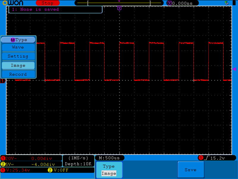
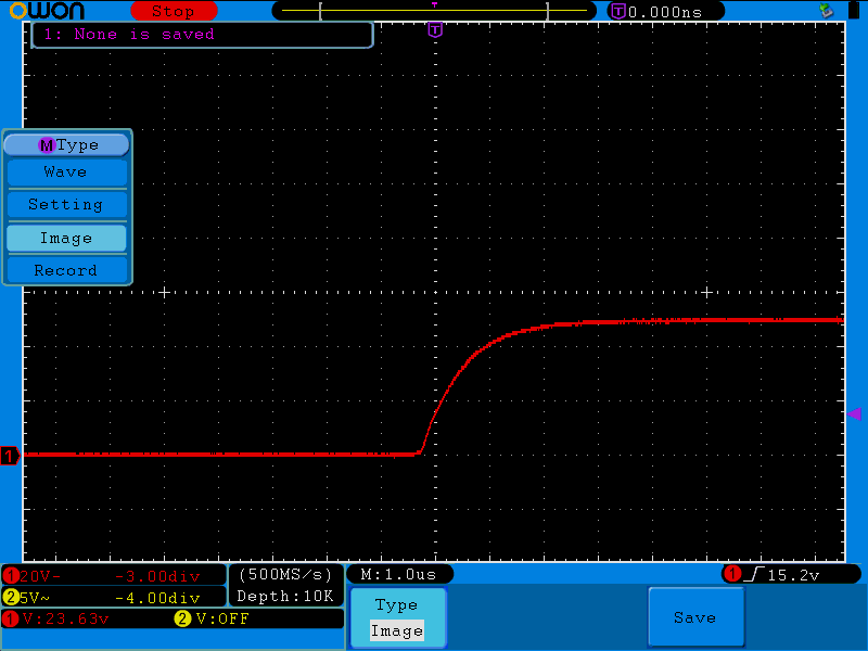
I attached a lead with an alligator clip to the reference oscillator but to probe setting is still 1:10, hence the 45V level.
The timebase is set to 500 μs/div and the trigger point is in the middle of the screen. Vertical settings are 2V/div (with a 1:10 setting this shows 20V/div) and the 0V line is in the middle of the screen.
- Start of display = 1200
- Display Length = 7600
- Sample size = 10000
- Timebase = 17 (500 μs/div)
- Vertical setting = 9 (2V/div)
- Attenuation = 1 (10x)
Owon-ref2
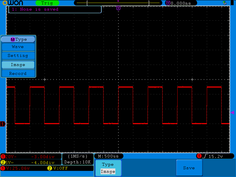
Compared to Owon-ref1 this file has the 0V line at 3 divisions below the center.
The only thing that changed in the header is the null offset:
- null offset = ffffffb5h or -75 which is 3 div below center.
In the sample data the levels are b5h (-75) for the lower line and f3h (-13) for the higher line. With a voltage level of 20V/div, this gives 20/25 = 0.8V/bit so the high level is -13 - (-75) = 62 * 0.8 -> 49.6V
Owon-ref4
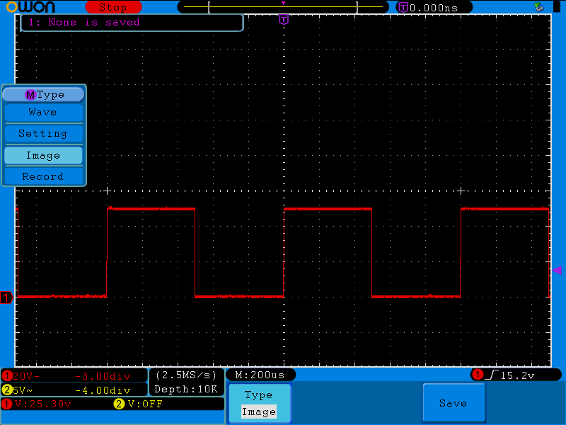
Compared to Owon-ref2 I changed the timebase to 200 μs/div.
- Timebase = 16 (200 μs/div)
- the number at offset 35h changed from 40200000h into 3f800000h which is exacly a00000h or 10M (as in 10x1024x1024).
Don't know what this means.
Owon-ref5
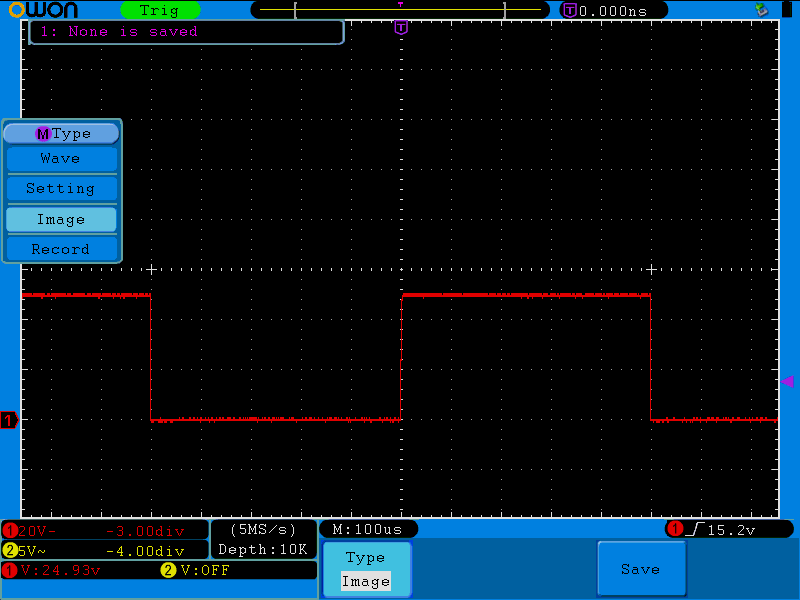
Again just a change in the timebase, now to 100 μs/div
- Timebase = 15 (100 μs/div)
- the number at offset 35h changed from 3f800000h into 3f000000h which is exacly 800000h.
Don't know what this means.
Owon-ref6
Again a time base change:
- Timebase = 9 (1 μs/div)
- the number at offset 35h changed from 3f000000h into 3ba3d70ah
- the numbers at offsets 39h and 3dh changed from 447a0000h into 00000000h
Owon Documentation
I received some documentation regarding the file format and the USB protocol that Owon uses. I guess I'll never use the USB protocol (I don't like to tether measurement equipment to my PC if it's not needed). Please not that this manual is not a complete dummies guide to Owon's dataformat but it does fill in some of the gaps of my own research.