Nederlandse versie
ESP8266 WiFi module
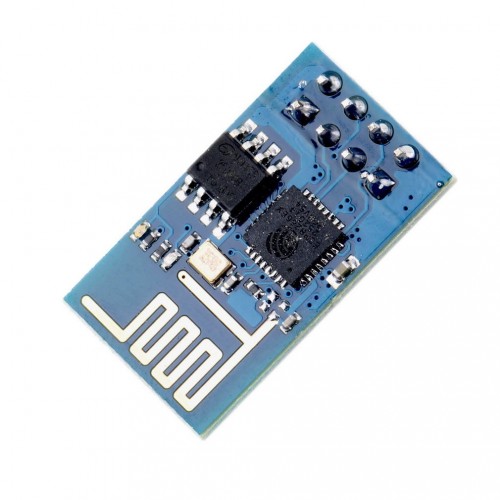
The ESP8266 module is a nice solution to give an embedded project WiFi access without too much hassle - and this all for a € 5,- budget.
But don't expect any magic from this module. It will give you network access on UDP or TCP level, that's all, the rest is up to you.
I got one module from TinyTronics to see how this module can be used and I quickly requested more. This seems the perfect solution to setup a dataconnection between PC and embedded target or between two embedded targets without any wires or the range limitations of BlueTooth.
There are a lot of project to be found on the internet telling you how to use this module. The WiFi temperature logger is a nice example in which data is send to ThingSpeak. Hackaday has a list of much more projects with this module.
In short: anything with data communication over a TCP port to another device (IP address) is doable. You can even place the module in Access Point mode to setup a direct connection between devices.
Old firmware
The modules are delivered with a fairly old firmware version. I had some problems with this firmware and in general this resulted in an unstable system.
This problem is easily solved by installing new firmware. An easy job once you get the correct tools and instructions 
Preparing for firmware update

First of all, you need to connect the module to a PC - A Windows PC that is - and connect the module to the PC using a USB-serial converter.
WARNING: The ESP8266 module only accepts 3.3V power supply and the I/O signals should also be 3.3V
Yes, I used this cheap PL2303 module with a 3.3V regulator but the Tx signal is a 5V signal and although this did not (seem to) damage my module I had some problems with communication errors.
I use this 5V to 3v3 level converter to make sure everything is OK.
Please check the picture at the right (click for a larger view) for all the connections. Note that the CH_PD signal must always be connected to 3v3, otherwise you will not be able to communicate with the module.
GPIO0 and Reset can be left unconnected in your embedded application, these signals are used to activate the programming mode.
First Contact
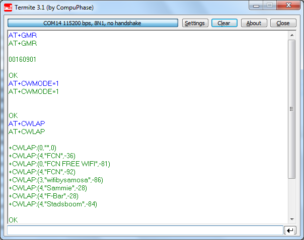
With GPIO0 and Reset not connected (or both at 3v3 level using a pullup resistor) you can communicate with the module. Standard baudrate is 115200 Baud with 8n1 settings.
The AT+GMR command will show the current API level (0016) and AT command set verion (9.1).
AT+CWMODE=1 sets the module in client mode and AT+CWLAP returns a list of all visible access points.
Updating the firmware
Connect the GPIO0 signal to Gnd and reset the module by pulling the reset pin low for a short interval. I simply use a wire connected to Gnd and touch the Reset pin - that's all you need.
Make sure you have a recent firmware version (I use v0.9.2.2) and the esp8266_flasher.exe tool.
Both can be found on this website following the links above. I know ... using a .exe file from an unknown site is a bit tricky. There should be an expressif website somewhere with the 'official' tool but I doubt if that will be more secure...
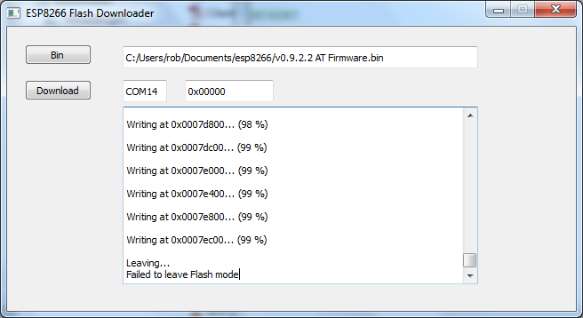
Just type the right COM port number in the text box (by hand - this is a very basic tool) and select the firmware.bin file. After that press "Download" and watch the magic happening.
If all you see is "connecting" in the text window, then most likely you have not pulled the GPIO0 pin low or forgot to reset after doing this. Or you still have the serial port open in another application. Make sure the GPIO0 pin is connected to Gnd, reset the module and disconnect any other terminal application.
The "Failed to leave Flash mode" message at the end seems to be standard. At this point it is safe to terminate the flash downloader and reset the module.
Do not forget to remove the wire from GPIO0, in normal operating mode this pin should not be tied to Gnd.
Check your new firmware
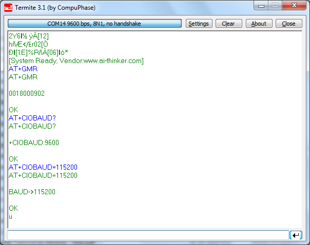
The baudrate of the new firmware is set to 9600 (don't ask me why!) so make sure you set your terminal program to 9600.
I check the firmware version with the AT+GMR command: API level 18 and AT command set v9.2.
Now set the baudrate back to 115200, or another baudrate you like, using the AT+CIOBAUD command. Now you should be able to communicate with the module at your new baudrate.
Cloud update
There is even a newer firmware version available but I was not able to find a file for this. It seems this newer firmware is only available as an online update.
For this, first make sure the module is in client or client and access point mode using the command "AT+CWMODE=1" or "AT+CWMODE=3".
Then connect to an access point that has an internet connection using the "join access point"command: "AT+CWJAP="ssid","passwd"" (replace ssid and passwd for the name and password of your accesspoint.
Now all you have to do is to type the "AT+CIUPDATE" command. You will then see a number of lines of text ("found server", "connect server", "got edition" and "start start"). I was able to do this a few weeks ago but with my new modules I was not able to get the "found server" message. It seems there is a problem with the server.
No problem: the 00180902 version of the software seems to work fine.
AT commands
Here are all the AT commands that I found.
Some commands are only available in a certain mode. The AT+CWLAP command is not available when the module is in Access Point mode. There are other commands that are only available when the Access Point mode or the station mode is active.
Just start playing around with this list of command. Also check out the projects at Hackaday, this will give you a fairly good idea of how to use this module.
| AT | General AT command | ||
| AT+RST | Reset device | ||
| \n\rOK\n\r | |||
| <info> | |||
| \n\rready\n\r | |||
| Note: there is no OK after "ready" | |||
| AT+GMR | Get firmware version | ||
| 19000902 | |||
| AT+CWMODE=<mode> | Set mode | ||
| <mode> | 1 - station | ||
| 2 - Access Point | |||
| 3 - Station & Access Point | |||
| AT+CWMODE? | Get mode | ||
| \n\r | |||
| +CWMODE=<mode> | |||
| AT+CWMODE=? | Mode command help | ||
| \n\r | |||
| +CWMODE:(1-3) | |||
| \n\rOK\n\r | |||
| AT+CWJAP="ssid","passwd" | Join Access Point | ||
| AT+CWJAP? | Get joined access point | ||
| +CWJAP:"ssid" | |||
| AT+CIFSR | Get Local IP Address | ||
| \n\r | |||
| <IP address> | |||
| \n\rOK\n\r | |||
| AT+CWLAP | List currently available Access Points (in mode 1 & 3) | ||
| \n\r | |||
| +CWLAP:(<ecn>,<ssid>,<rssi>,<mac>,<chl>)\n\r | <ecn> | 0 - open, no security | |
| 1 - WEP | |||
| 2 - WPA_PSK | |||
| 3 - WPA2_PSK | |||
| 4 - WPA_WPA2_PSK | |||
| <ssid> | "device-name" | ||
| <rssi> | RSSI value (number) | ||
| <mac> | MAC address, e.g. "70:4d:d2:a9:a3:2f" | ||
| <chl> | Channel (number) | ||
| … repeat for each access point found | |||
| \n\rOK\n\r | |||
| AT+CWQAP | Exit connection with the AccessPoint | ||
| \n\rOK\n\r | |||
| AT+CWSAP=<ssid>,<pwd>,<chl>,<ecn> | Set AccessPoint parameters | ||
| \n\rOK\n\r | <ssid> | "ssid" | |
| <pwd> | "password" (only valid when ecn not 0) | ||
| <chl> | channel (number) | ||
| <ecn> | 0 - open, no security | ||
| 1 - WEP | |||
| 2 - WPA_PSK | |||
| 3 - WPA2_PSK | |||
| 4 - WPA_WPA2_PSK | |||
| AT+CWSAP? | Get AccessPoint parameters | ||
| \n\r | |||
| +CWSAP:"ssid","passwd",<chl>,<ecn> | |||
| \n\rOK\n\r | |||
| AT+CWLIF | Get IP address for client (only when client connected) | ||
| \n\r | |||
| <IPv4>,<Mac> | <IPv4> | 100.168.4.100 | |
| \n\rOK\n\r | <Mac> | d8:90:e8:9e:6d:56 | |
| Note: line with IP addresses is omitted when no client connected | |||
| multiple lines with IP addresses when multiple clients connected | |||
| AT+CIPMUX=<mode> | Start multiple connections | ||
| <mode> | 0 - single connection mode | ||
| 1 - multi connection mode | |||
| AT+CIPMUX? | Get multiple connection mode | ||
| \n\r | |||
| +CIPMUX:<mode> | |||
| AT+CIPSERVER=<mode>,<port> | Configure a server | ||
| <mode> | 0 - off server mode | ||
| 1 - open server mode | |||
| <port> | Port | ||
| AT+CIPSTATUS | Return server status | ||
| \n\r | |||
| STATUS:<status> | <status> | ||
| +CIPSTATUS:<id>,<type>,<addr>,<port>,<???> | <id> | ID number of connection (0-4) | |
| <type> | "TCP" or "UDP" | ||
| <addr> | IP address | ||
| <port> | port number | ||
| <???> | |||
| AT+CIPSTO=<timeout> | Set automatic socket client connection timeout | ||
| <timeout> | timeout in seconds | ||
| AT+CIPSEND=<id>,<length> | Send data | ||
| <id> | connection ID (omitted of CIPMUX=0) | ||
| <length> | number of bytes to follow | ||
| Note: ESP8266 sends ">", then respond with length bytes | |||
| +IPD,<id>,<length>:<data> | Receive data | ||
| <id> | connection ID (omitted if CIPMUX=0) | ||
| <length> | number of bytes to follow | ||
| <data> | received data | ||
| AT+CIOBAUD=<baudrate> | Set baudrate | <baudrate> | 9600 .. 115200 |
| \n\r | |||
| BAUD-><baudrate> | |||
| \n\r | |||
| AT+CIOBAUD? | Get baudrate |